Page 167 - Emeraude 2.60 Tutorial
Basic HTML Version

Emeraude v2.60 – Doc v2.60.01 - © KAPPA 1988-2010
Guided Interpretation #8 • B08 - 23/25
Select the Interpretation method to ‘Continuous’ and validate with OK.
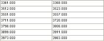
Define the calculation zones in stable regions: use the manual definition
and enter:
Fig. B08.29 • Calculation zones
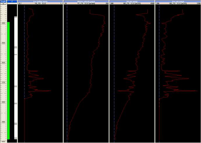
Setup the screen for interpretation with the layout:
[Depth – Z – Gas holdup match – Mixture velocity match – Oil rate match - Gas rate match]
Fig. B08.30 • Data display for interpretation
Go to Inflow Rates. The selected model is 3 Phase L-G. The selection of correlations is
irrelevant as they will be by-passed in this case: more explanations below.
Click on OK. You are taken to the Contributions screen (see below).
Click left mouse button down on the Contribution cell for the Bottom zone, and set it to No
Flow by selecting ‘Closed zone’.
Set all other contributions to Positive.
Tick ‘Match surface conditions’.
Uncheck ‘Constrain slippage sign’ and press ‘Global Improve’.
After the first iteration the schematic logs appear on the screen and the successive changes are
visible on all the tracks (you may have to move the Zone rates dialog to see the changes).

