Page 21 - Emeraude 2.60 Tutorial
Basic HTML Version


Emeraude v2.60 – Doc v2.60.01 - © KAPPA 1988-2010
Guided Interpretation #1
•
B01 - 19/38
The ‘Interpretation Settings’ dialog appears, Fig. B01.19. The first tab allows to specify the
interpretation mode (Zoned or Continuous), the way the calculations are initialized, and the
spinner calibration. Interpretation modes are described in more details in Guided Session#3; in
this first session we will use the defaults. The ‘Calibration’ drop list gives access to the
calibration mode [None – Individual]. The ‘Individual’ spinner calibration mode is the default
and allows selecting individually the spinners to calibrate. Depending on the calibration mode,
the table beneath allows selecting the spinner tools for calibration. Note: if several spinners
have been run together, an inline and a fullbore spinner for instance, the ‘Individual’
calibration mode allows using both in the same interpretation. Before defining the reference
channels we will save the screen layout for later use.
Click OK without defining any reference channels.
Tile the plots if necessary.
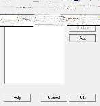
Click the snapshot button , store current screen.
Click Add to create ‘Capture 1’ with the defaults
Fig. B01.21a • Snapshot Manager
Fig. B01.21b • Adding a new snapshot
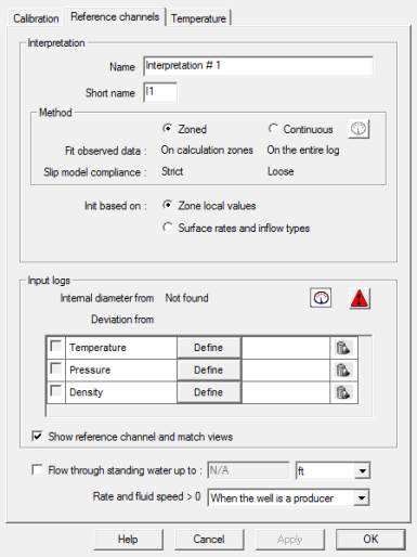
The reference channels can be
defined in the second tab of the
Interpretation settings dialog, Fig.
B01.22.
Click on the ‘Information’ button
and select the ‘Reference channels’
tab.
If the well internal diameter has not
been defined, a red warning appears
in the Interpretation Settings dialog,
in front of the internal diameter
information string, to warn the user.
Fig.
B01.22
•
Reference Channels

