Page 81 - Emeraude 2.60 Tutorial
Basic HTML Version
Emeraude v2.60 – Doc v2.60.01 - © KAPPA 1988-2010
Guided Interpretation #4
•
B04 - 7/14
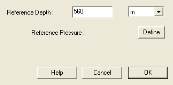
Click on ‘Parameters’ and define the reference depth at 560 m.
Fig B04.10a&b • S.I.P. parameters
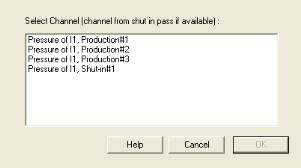
Click the ‘Define’ button in the dialog to select Shut-In #1 for the reference pressure.
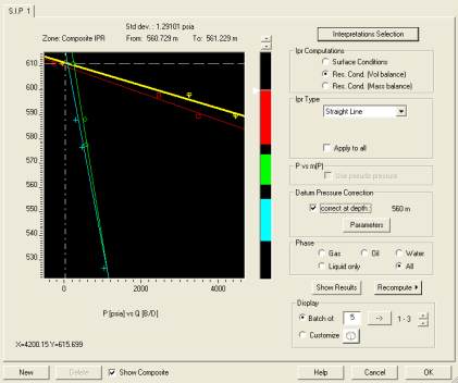
After validating your inputs, click the box ‘correct at depth:’… When all pressures are corrected
to a common datum, all the inflow curves (here the lines) should cross the Y axis at the same
location. A discrepancy is representative of cross-flow. In the Shut-in #1 survey the spinner is
certainly not stable causing the difference.
Fig B04.11 • S.I.P.
B04.4 • Temperature
On Production #1, we will redo the interpretation but instead of using the Apparent Downflow
model inside the casing we will use the temperature.
In survey Production #1, create a new interpretation #2 from Interpretation #1. Select the
PVT, the spinner calibration and the input channels for copy. Do not copy the calculation
zones.

