Page 87 - Emeraude 2.60 Tutorial
Basic HTML Version
Emeraude v2.60 – Doc v2.60.01 - © KAPPA 1988-2010
Guided Interpretation #4
•
B04 - 13/14
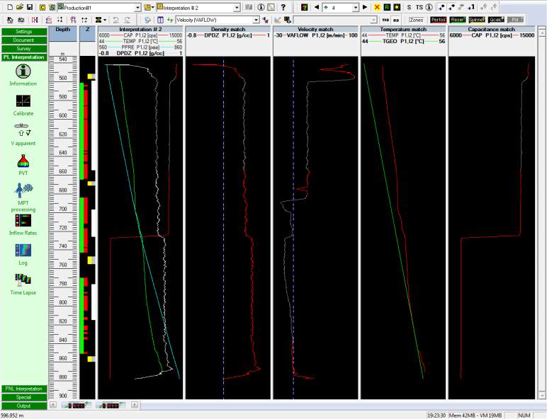
The top of those 3 curves shows large variations and would probably deserve more editing but
we will leave them unchanged in our case.
Fig B04.19 • After hiding parts on VAFLOW, DPDZ, CAP
Inflow Rates
Select ‘Inflow Rates’.
Select 3-Phase L-G; accept the defaults (Dukler and ABB-deviated) with OK.
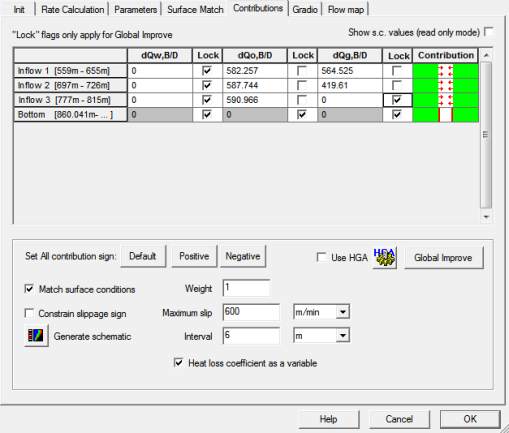
You are driven to the ‘Contributions’ tab, because the Continuous method was selected. It can
be seen that the bottom zone has been set to ‘No Flow’ automatically.
Check ‘Match surface conditions’.
dQw is 0 for all zones; lock those
values (you can click on the ‘Lock’
header button to lock all of them at
once).
Set dQg= 0 for inflow 3 and lock.
Check ‘Heat loss coefficient as a
variable’.
Uncheck ‘Constrain slippage sign’
Select ‘Global Improve’. You can see
the schematics updated during the
nonlinear regression.
Exit ‘Zone Rates’, Fig B04.21.
Fig B04.20 • Contributions tab

