Page 96 - Emeraude 2.60 Tutorial
Basic HTML Version


Emeraude v2.60 – Doc v2.60.01 - © KAPPA 1988-2010
Guided Interpretation #5 • B05 - 8/32
B05.4 • Survey – Tool info
Go to ‘Survey’ – ‘Tool info’, the second
tab gives the list of Multiple Probe Tools
found in the current survey. The list
shows here as expected DEFT (DFBx),
DEFT 5-8 (DFBx), DEFT (DFHx), and
DEFT 5-8 (DFHx).
Probe status
For each particular tool the probe status
can be assigned in the grid as either
‘Active’, ‘Disable’, or ‘Ignore’. The status
influences the bubble/holdup images and
also the reference channel processing.
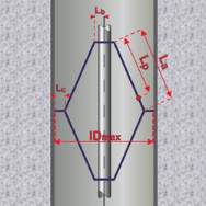
Tool Geometry :
Geometric parameters are entered at this
level: Lp/La, Lb, Lc and IDmax; they are
defined in the ‘Schematic’ dialog opposite.
For some tools, a predefined geometry can
be selected using the button
.
Select the ‘DEFT (DFHx)’, and then
enter Lp/La = 0.75, Lb = 0, Lc = 0, and
IDmax = 11 in.
The tool geometry is not required for the
creation of image views.
The geometry must be defined:
To visualize cross-sections of the
wellbore.
Process the data (further next).
Fig. B05.9 • Tool information
Fig. B05.10 • Schematic

