Page 106 - Emeraude 2.60 Tutorial
Basic HTML Version
Emeraude v2.60 – Doc v2.60.01 - © KAPPA 1988-2010
Guided Interpretation #5 • B05 - 18/32
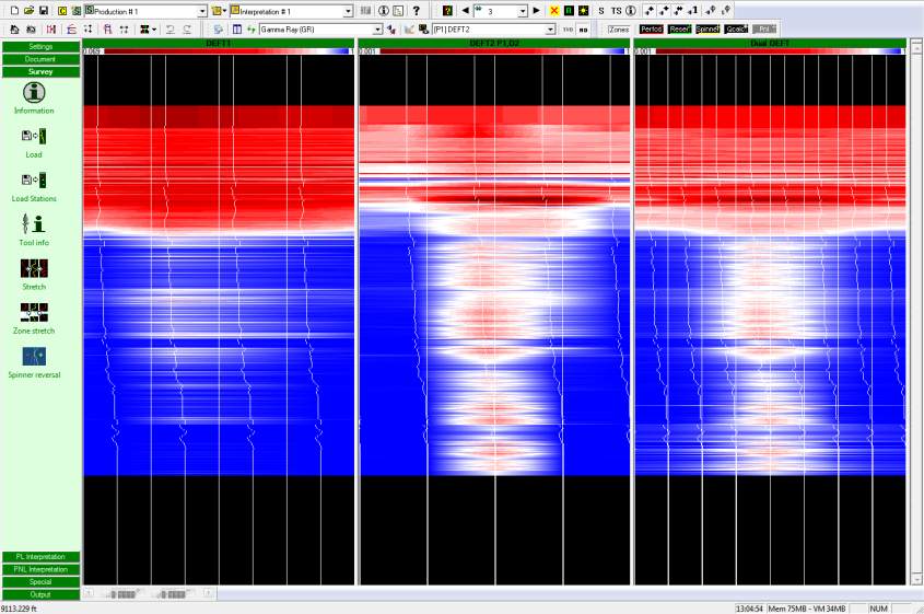
Fig. B05.21 • Image views for pass down2: DEFT1, DEFT2, and Dual DEFT
The dual image shows some discontinuities going from the reading of one tool to the other,
which is expected when looking at the images for DEFT1 and DEFT2 next to each other.
Nevertheless, we will accept this difference as we will eventually average all the probe
readings (except DFH4). We will see later in the interpretation if this assumption was valid.
Looking at the image alone it may be difficult to know the location of the various probes. This
can be seen by a right click on the image view, and selecting the ‘Cross-section’ option. This
option brings up the dialog shown below. With the dialog on the screen, if you press the ‘Shift’
key and move the mouse inside the image view, you will see a continuous update of the probe
position and the interpolated holdup circumference.
Note: Access to the cross sections requires the definition of the geometric parameters, for the
particular tool; this is entered in ‘Multiple probe’ tab of the ‘Survey – Tool info’. Set all DEFT
tools geometry identical: Lp/La = 0.75, Lb = 0, Lc = 0 and IDmax = 11 in.
The cross section will be drawn differently depending on the selected average holdup
calculation type:

