Page 148 - Emeraude 2.60 Tutorial
Basic HTML Version

Emeraude v2.60 – Doc v2.60.01 - © KAPPA 1988-2010
Guided Interpretation #8 • B08 - 4/25
In this mode, each FSI spinner will be calibrated the same way the conventional spinner is. We
must therefore create the calibration zones. Considering the data, one zone is enough.
Create a spinner calibration zone on the interval [1470m, 1480m].
Go to the Calibrate option.
Go through the spinners in turn (you can use the arrows next the spinner drop list to do
so).
SPIF0: slopes are OK, set the thresholds from the intercepts.
SPIF1: slopes are OK, set the thresholds from the intercepts.
SPIF2: dead.
SPIF3: disable the point for pass down 1, recalculate positive line, set the
thresholds from the intercepts.
SPIF4: set the thresholds from the intercepts.
SPIN: set the thresholds from the intercepts.
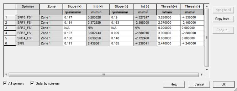
If you press ‘All results’, a window pops up showing the active spinner slope and threshold for
the selected zone. If you select ‘All spinners’, the different spinners slopes and thresholds are
displayed (see below) and can easily be adjusted.
Fig. B08.5 • Spinners results
Quit this window and the calibration with OK.
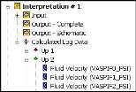
Generate the apparent velocities for all spinners with the defaults.
The resulting channels appear in the browser in a ‘Calculated Log Data’ sub-folder of the
interpretation node.
Fig. B08.6 • Spinner apparent velocities

