Page 157 - Emeraude 2.60 Tutorial
Basic HTML Version
Emeraude v2.60 – Doc v2.60.01 - © KAPPA 1988-2010
Guided Interpretation #8 • B08 - 13/25
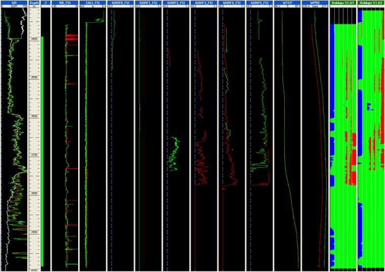
Fig. B08.19 • Optical probes display with image views
Note that velocity views are also possible but we will see that later in this document.
As decided earlier, we will now ignore the probe GHHF1 and spinner SPIF2.
Go to Survey – Tool Info, ‘Multiple probe’ tab.
Select the FSI in the tool list.
Set SPIF2 and GHHF1 to ignore.
Note that, since the beginning, snapshots have been created although there was no existing
interpretation. Such snapshots are labeled with the survey short name preceeding their name
(e.g. ‘[Fl] PSP Basic Sensors’). They will be available for any interpretation created later. If such a
snapshot is modified by adding a view created under an interpretation or containing interpretation
dependent data, the snapshot name will change with the short name of the interpretation
replacing the short name of the survey (e.g. ‘[I1] PSP Basic Sensors). Such a snapshot will then
only be available when Interpretation I1 is active.
B08.3 • Flowing Survey: Data Interpretation
The review of the sensor measurements done above helped us deciding which data will be used:
spinner and optical probes for the FSI, none from the PFCS and possibly all conventional tools.
The data from the FSI must now be processed to generate averages, according to criteria chosen
by the user. These average outputs will then be used as inputs for the interpretation and the
interpretation done as for conventional tools.
Create a new PL interpretation.

