Page 49 - Emeraude 2.60 Tutorial
Basic HTML Version


Emeraude v2.60 – Doc v2.60.01 - © KAPPA 1988-2010
Guided Interpretation #2
•
B02 - 9/22
B02.3.4
8B
• Creating a new interpretation
Move to the ‘PL Interpretation’ panel.
Select the ‘Information’ icon.
This is the first interpretation for the active survey: an interpretation is created automatically,
called Interpretation#1.
Note: To create a new interpretation after one exists, you need to use the ‘Create a new
Interpretation’ icon
in front of the interpretation drop list of the main toolbar.
Leave this name unchanged and validate with OK.
In the ‘Reference channels’ tab of the ‘Interpretation Settings’ dialog, Define the reference
Temperature as that of Down#1.
Define the reference Pressure as an average of All pressure passes during the Shut-in.
Define the reference Density as an average of All the density passes except Up3 and
Down3.
Press OK to confirm.
B02.3.5
9B
• Spinner calibration and apparent velocity
Use the Spinner Calibration zone option
of the zone toolbar to define one zone
above the top perfo and one below the deepest (Fig.B02.10).
Click on ‘Calibrate’.
In the calibration, Action for All zones, set all positive slopes to the average positive slope.
Also set all negative slopes to the average of the negative slopes (Fig B02.11).
There is a discrepancy between the estimation of apparent velocity from the Up and Down
passes because of the well deviation. It is not possible from the calibration alone to determine
the value of the thresholds and in this case, we will leave them both at 0.
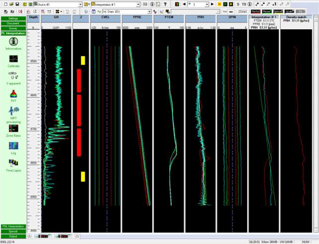
Fig. B02.10 • Two calibration zones defined

