Page 76 - Emeraude 2.60 Tutorial
Basic HTML Version
Emeraude v2.60 – Doc v2.60.01 - © KAPPA 1988-2010
Guided Interpretation #4
•
B04 - 2/14
Production #2 illustrates the profile obtained in this well (you can activate this survey to see
the interpretation). The combination of the well deviation, the large casing diameter, and the
large water holdup at the bottom of the well creates favourable conditions for phase re-
circulation inside the casing. It can be seen that the complete log, everywhere faithful to the
data, exhibits only downflow of water inside the casing. The schematic however, is showing
upflow of oil in that zone. This result was obtained using the Apparent Downflow option of
Emeraude, which is illustrated in the section below.
An alternative, described in section B04.4, is to use the temperature quantitatively. In any
case, a proper interpretation of the data inside the casing can only be obtained by disregarding
the spinner in that section.
B04.1.1 • Production#1 Interpretation
Reference channels for pressure, temperature, and capacitance have already been produced.
We will first create a pseudo-density channel from the pressure.
Make sure you return to Production #1.
Open the data browser; then the nodes Production #1, Interpretation #1, Input. Select the
Pressure channel and then the icon
f’
(or the ‘Derivative’ option in the popup menu).
Enter smoothing = 2m.
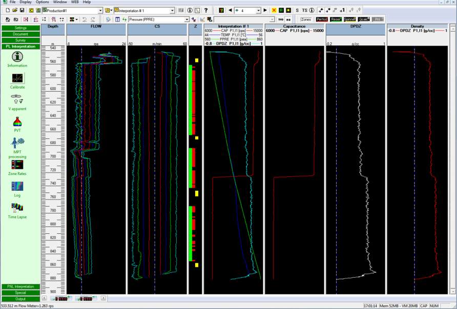
2 new tracks appear at the right: one titled ‘DPDZ’ and the match track labelled ‘Density’. The
density is also added to the Interpretation #1 view.
Fig B04.2 • Pseudo-density channel created

