Page 98 - Emeraude 2.60 Tutorial
Basic HTML Version
Emeraude v2.60 – Doc v2.60.01 - © KAPPA 1988-2010
Guided Interpretation #5 • B05 - 10/32
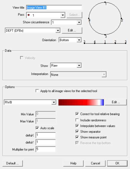
Fig. B05.12 • Image view creation
The ‘Image View’ dialog allows the definition of:
A specific title.
The tool to be used from the list defined in the ‘Survey’ – ‘Tool Info’ dialog still accessible
via the ‘Edit’ button.
The particular pass or combination of passes to display in the image.
The tool orientation, defined as the position of an imaginary user looking at the tool: from
the top, the bottom, the left side or the right side (top and bottom could be reversed for
the two last choices).
The data to use (raw or reconstructed, more on this next) and from which interpretation.
The image view color scale.
At this stage, you can recall the ‘Tool info’ and/or the ‘Color scale’ dialogs (via the ‘Edit’
buttons) in order to view/edit the current options. Other controls specific to the image view
are:
‘Min’ and ‘Max’ define the scale range - if ‘Auto Scale’ is checked, taken as the channel
bounds.
‘deltaX’ & ‘deltaY’ define the horizontal & vertical resolution in pixels. A multiplier is used
for print.
‘Correct for tool relative bearing’ corrects the image for the tool rotation using the relative
tool bearing: the center of the view represents the top of the well.
Include randomness: when the image is drawn using interpolation between two neighbor
probes, this option adds random variations around the linear trend.
‘Interpolate between values’: create a linear interpolation between two consecutive probe
measurements.

