Page 99 - Emeraude 2.60 Tutorial
Basic HTML Version
Emeraude v2.60 – Doc v2.60.01 - © KAPPA 1988-2010
Guided Interpretation #5 • B05 - 11/32
‘Show separator’: show vertical lines splitting the track in as many intervals as there are
probes.
‘Show measure point’: shows the probe position (undulating white line on the view in the
middle of each track).
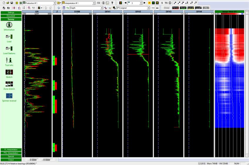
Select DEFT (DFHx) for the tool, and Pass Down 2, and validate. The image view is created,
Fig B05.13:
Fig. B05.13 • First image view created
An image corrected for relative tool bearing shows the top of the pipe at the center of the
view. The view below indicates water at the top only because we included DFH4 in the image
and this channel is erroneous. Note that you can also create a bubble count image in the same
manner.
As an exercise, you can change the view orientation to see the change. Then, set back the
orientation to ‘Bottom’.

