BHP Workflow
The BHP workflow converts pressure measured at a certain gauge depth to the pressure at the desired depth, usually converting Well Head Pressure (WHP) to Bottom Hole Pressure (BHP). To create a BHP workflow, some essential information is required, including Wellbore and PVT objects, specific well properties, pressure gauge and rates. For gas lift cases, additional information must be provided, including PVT data and gas injection rates.
The BHP workflow assumes, by default, that the flow path is through the tubing when the wellbore configuration includes a defined tubing string and a Tubing Head Pressure (THP) is available. If tubing is not defined, the workflow defaults to assuming flow through the casing, using the Casing Head Pressure (CHP) as the reference for pressure calculations. When the flow path is known, it should be defined during the wellbore creation.
Temperature is linearly interpolated with measured depth (MD) between the known wellhead and bottomhole temperatures. This approach accounts for wellbore deviation since measured depth follows the actual well path. As a result, the temperature profile is generally nonlinear when expressed against true vertical depth (TVD) in deviated wells.
The pressure at the target depth is estimated using various correlations, The available flow correlation options depend on the selected PVT fluid type, as shown in the table below:
Fluid Type | Has Water | Available correlation |
Saturated oil Volatile Oil Volatile Oil | Yes No No | |
Dead oil | Yes No | |
Dry Gas Wet Gas | Yes | |
Gas (Condensate Wet and Dry) | Yes |
Prerequisites
The following conditions must be met prior to executing the BHP workflow:
A Wellbore object exist under the well.
A PVT object is defined under the well.
The required properties are defined under the well properties.
BHP workflow activation
The BHP workflow is activated when a wellbore object is created. For time-dependent completions, where the wellbore geometry changes over time, a separate geometry must be defined for each date on which a change occurs. This ensures an accurate representation of the well throughout its productive life.
Inputs
To run the BHP workflow, the following information must be provided:
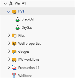
PVT
Define the PVT object for any reservoir fluid. The PVT object is created via the PVT service, which extracts PVT data from any STR document. For gas lift cases, a separate PVT object must also be defined for the injected gas.
Pressures gauges
At least one pressure gauge must be provided, either Casing Head Pressure (CHP) or Tubing Head Pressure (THP). For time-dependent completions, where the flow path changes from casing to tubing, both CHP and THP are required.
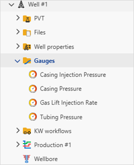
Rates gauges
Define the input surface rates gauges: oil rate (qo), gas rate (qg), water(qw). For gas lift cases, also define the injection rates gauge (qgi).
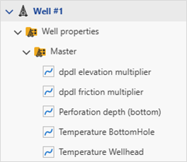
Well properties
The BHP workflow requires specific well properties. These properties are mandatory and the workflow cannot be executed if any are missing.
Thermal Properties: The following temperature parameters must be defined:
Wellhead Temperature (WHT)
Bottomhole Temperature (BHP)
Flow Type Parameters: The following multipliers must be specified to account for pressure loss due to elevation and friction:
dp/dl Elevation Multiplier.
dp/dl Friction Multiplier.
If the multipliers are not defined, they will be assigned default values of 1.0.
Target Depth: Pressure conversion requires at least one depth value to be defined in the Well Properties. This can include perforation depth, reservoir depth, or any other reference depth.
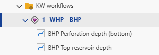
Viewing BHP Workflow Results
When BHP workflow is first launched, it will create a new folder called KW workflows in the field hierarchy, with the BHP Workflow results listed there. Depending on the selection of output gauges when creating the BHP Workflow, the computed pressures are created under the parent well:
One can run several workflows in parallel and compare them.
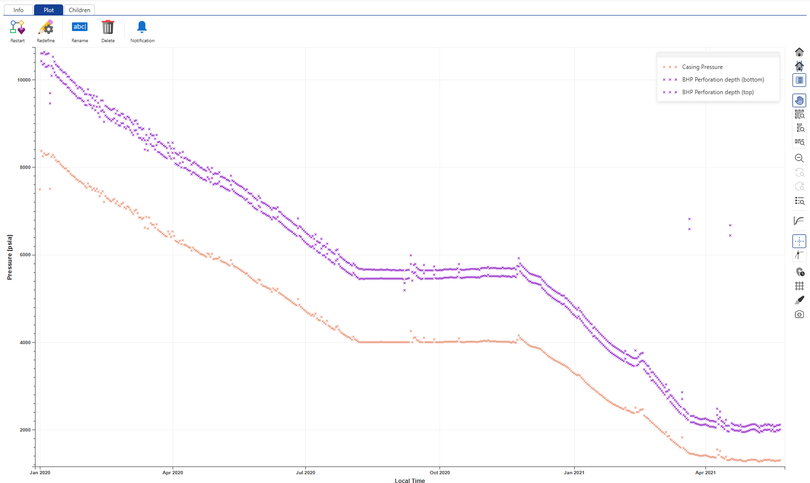
BHP Workflow plot
It is also possible to view the BHP Workflow result as a plot. To do so:
In the well node, click on the workflow folder.
Click on BHP Workflow node, then switch to the plot tab.
In this plot, you can see input pressure and outputs.
 |