Creating BHP Workflow
The BHP workflow starts with a Wellbore, PVT Objects, and Specific well properties. The workflow can then perform pressure conversion from a given gauge depth to the required datum for the selected pressure gauge. See BHP Workflow for more details.
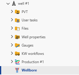
A Wellbore object must exist under the well.
A PVT object must exist under the well.
The required properties are defined under the well properties.
Under the Well level click on Wellbore node:
Under info tab click on
 .
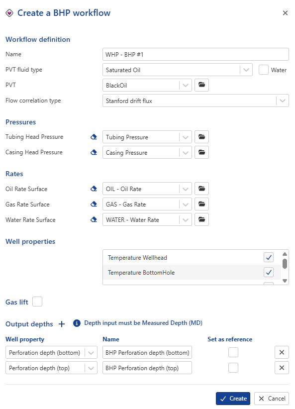
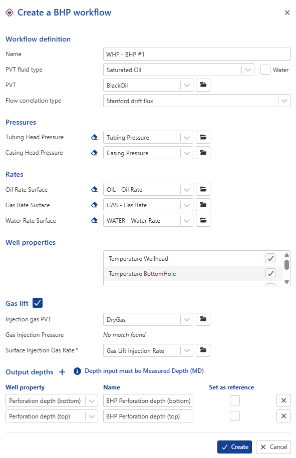
.This will launch the following BHP dialog:
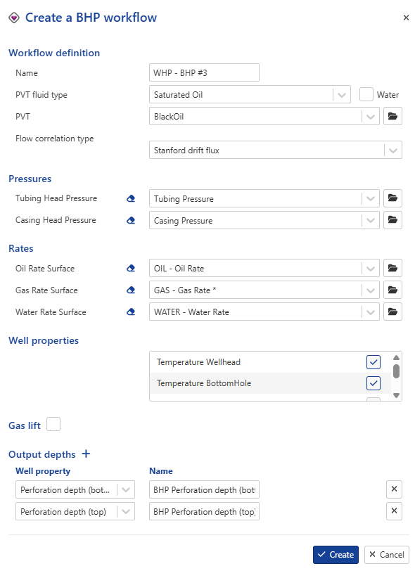
Give the BHP workflow a Name.
Select the PVT object to use for this BHP Workflow ,by default, it will be set to the first object extracted under the well.
Choose the appropriate flow correlation type. (The available flow correlation options depend on the selected PVT fluid type. See BHP Workflow for more details)
Select the Pressures input gauges and select the Rates gauges.
Note
Downhole pressure gauges are supported as inputs for the BHP workflow
Mandatory well properties (dpdl elevation multiplier, dpdl friction multiplier, Temperature Wellhead and Temperature Bottomhole) are locked and cannot be deselected.
If Gas lift checkbox is checked:
Select the injected gas PVT.
Select the gas injection pressure (optional).
Select the gas injection rate.
Select the one or multiple Output depths from well properties. Each output gauge can be assigned a custom Name.
Click on Create .
Gas Lift Option
The Gas Lift option is designed to calculate bottomhole pressures in wells operating under gas lift conditions. It integrates gas injection parameters, injection depth, wellbore geometry, and injection gas properties to provide accurate pressure profiles along the wellbore. It is essential to configure the inputs properly for accurate BHP calculations.
Required inputs
To enable the Gas Lift functionality, the following inputs must be defined:
Injection gas PVT: This defines the injected gas properties and is mandatory for all gas lift scenarios.
Surface Injection Gas Rate: Indicates the gas injection rates at the surface. This parameter is mandatory for the BHP calculations in gas lift cases.
Gas Injection Depth
The BHP workflow supports two configurations for gas injection depth:
No gas lift valve depth provided: If no depth is specified, the BHP workflow assumes gas is injected at the bottom of the tubing.
Gas lift valve depth provided: If the depth of the gas lift valve is known, it should be defined in the wellbore object under Gas Lift Valve section.
Gas Injection Pressure
The gas injection pressure is an optional input. This input is typically used for estimating injection depth during design, but it has no effect on the BHP calculations.
Gas lift reference table
Parameter | Required | Remarks |
|---|---|---|
Injection Gas PVT | Yes | |
Surface Injection Gas Rate | Yes | |
Gas Injection Pressure | Optional | |
Gas Lift Valve Depth (MD) | Optional | Define injection depth if known |
 |
Output
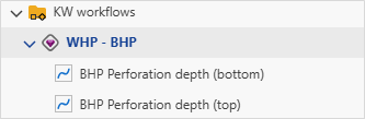
Once the BHP workflow is launched, a new folder called KW workflows is created in the field hierarchy. All output results generated by the BHP workflow are stored inside this folder.
To visualize a specific output:
Navigate to the KW Workflows folder.
Select the desired output from the list.
The selected output will be displayed in the output plot channel.
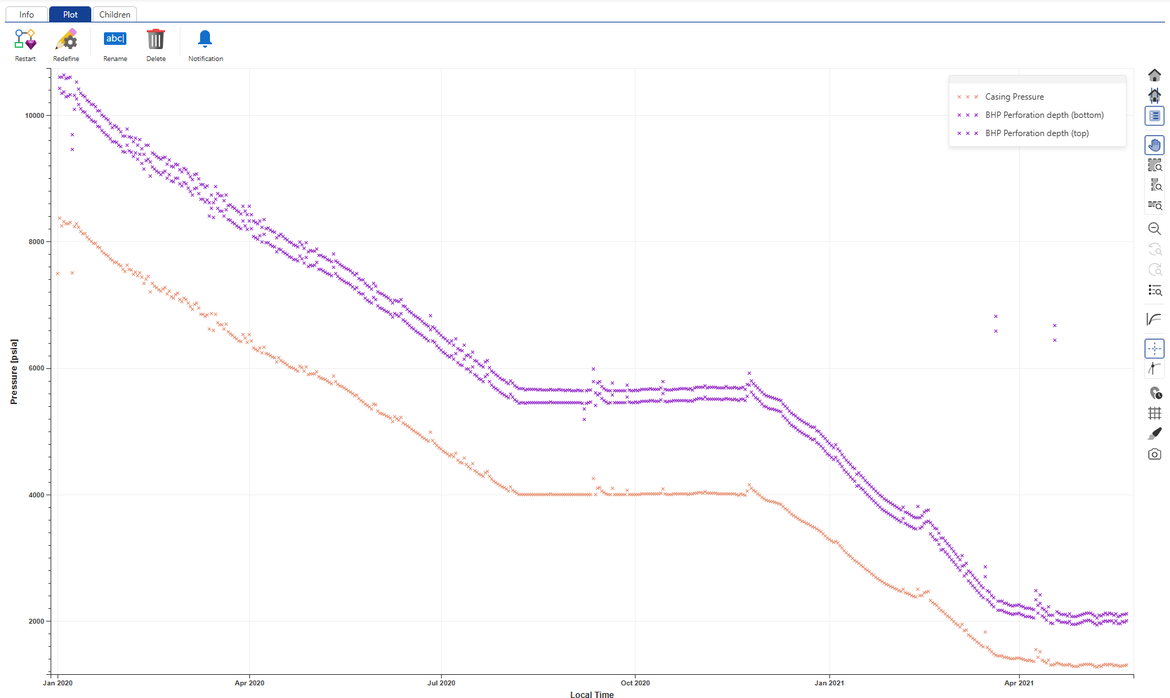
BHP Workflow Output
The BHP workflow plot shows:
Input WHP: The wellhead pressure (WHP) input, whether measured from the casing or tubing gauge, is available for visualization in the BHP workflow output plot channel.
Computed BHP: Converted bottomhole pressures can be displayed alongside the input pressures for comparison. To visualize the computed BHP, navigate to the BHP workflow node and select the corresponding output option.