Analytical models
SRVB Model
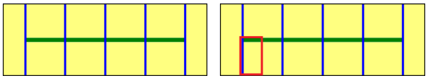
The hypothesis for the SRVB model is that the reservoir is geometrically limited to the area defined by the series of fractures. The reservoir size along the horizontal drain is increased on each side by half of the fracture spacing to provide the same diffusion area for the fractures at the end of the well.
Because of the symmetry of the problem, each fracture has strictly the same contribution and a solution can be generated focusing on only one symmetry element corresponding to a quarter of the drainage volume of a given fracture (see below). By the use of the symmetry element, both analytical and numerical solutions are extremely fast, the speed not being dependent on the number of fractures. Once the elementary system has been simulated, the instantaneous rates are multiplied by 4. Nf to get the answer of the global SRVB system.
 |
The simplistic model has been extensively used by other technical groups as their reference analytical model. It does not account for diffusion beyond the SRB, which is generally acceptable during the first years of production. Understandably, for a given well the EUR will be conservative.
Trilinear Model
This is an extension of the SRVB model to which a linear flow was added from outer unstimulated, reservoir matrix zone toward the inner SRV zone. Petrophysical properties (permeability, porosity, rock compressibility...) may be different in the two zones. Because of the influx from the outer zone, this model may be considered an intermediate between the SRV model and the 'classic' model.
As for the SRV model, the trilinear can be solved by focusing on a single symmetry element (see below) corresponding to a quarter of the drainage area of a given fracture. In both analytical and numerical cases, the speed is very high and not dependent on the number of fractures.
Multi-Zone Fractional Dimension Model
This approach presents a way to analytically model transient behavior of a complex fracture network.
The method presented by Acuna (2016) allows interpreting pressure and flow rate behaviors observed in unconventional wells that do not exhibit linear flow regime. The method suggests a way to diagnose multiple flow regimes (sub-linear, linear, sub-radial) on the standard loglog plot.
A multi-fractured horizontal well in a fractured formation can be compared to a fractured well (with the fracture length equal to the sum to all initially connected high conductivity fractures) that drains a reservoir with a flowing area A, that is perpendicular to the flow and changes with distance according to the power law:
Where,
Xf is the half flow area width
r is the distance and is taken as the fracture half length
and
σ is the half flow dimension.
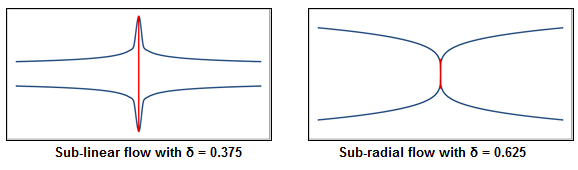
Note that in the case of σ = 0.5 the flow regime is linear and the flowing area becomes constant with respect to the distance to the fracture area, i.e. the case reduces to the channel geometry. Also the case of σ = 1 is a classical radial flow, and σ = 0 corresponds to the PSS. σ This generalized model is versatile as it includes the cases with:
The flow area A decreasing with the distance from the fracture (sub-linear flow, values of 0 < σ < 0.5, below, left), and
The flow area A increasing with the distance from the fracture (sub-radial flow, values of 0.5 < σ < 1, below, right).
The dimensionless pressure is shown to have the following form:
And its log pressure derivative can be written as follows:
Hence during this flow regime the pressure and the derivative are functions of the time raised to the power (1 - σ), which can be reliably diagnosed on a loglog plot by two parallel straight lines with a slope (1 − σ), which directly provides the fractional dimension value and gives an insight into the nature of the fractures network geometry.
The production of a Discrete Fracture Network system with its complex geometry can lead to a sequence of different flow regimes, depending on the drained and investigated area.
 |
The sub-linear case might represent a MFHW in a densely fractured reservoir, when the areas drained by each fracture reduce with distance because of fractures interference. On the other hand, the sub-radial case might correspond to a network of fractures of both high and low conductivity, the latter having drainage area that increases with distance in a more pronounced way.
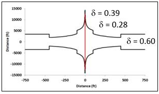
Also, the presence of fractures of different conductivity and their geometrical proximity can result in a system that exhibits a sequence of linear, sub-linear, radial, sub-radial flow regimes. This is illustrated below in terms of reservoir model geometry and corresponding δ versus distance from the fractured area.
 |
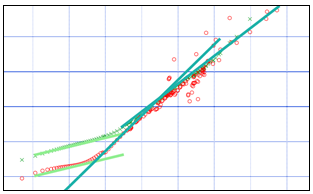
This type of geometry gives a sequence of straight lines on the loglog plot.
 |
The multi-zone fractional dimensional model concept presents an extension of the described model to n zones characterized by their individual parameters and sizes. The outer boundary of the last zone can be defined as infinite, no-flow or constant pressure.
Model Parameters
Solution type | The external MZFD model offered two solution types: Image well and Direct composite. Only the direct composite model was implemented in the standard MZFD model and therefore the choice to switch between the two is not available. |
Boundary type | Can be set to none, no flow and constant pressure |
Minimal distance | Start of area calculation |
Total fracture half-length | nXf in case of multiple fractures |
Skin | Mechanical skin |
Number of zones | n |
Fractional dimension | σ the half flow dimension |
Outer radius | Distance of end of the zone “n” (if > 1) |
Interface area control type | Used for the following zone area calculation consistency. Can be set to 'Consistent volume (behind)', 'Consistent area (front)' or 'User input' (see 'Interface area control factor' below) |
Interface area control factor | Available if the 'Interface area control type' is set to 'User input', this is a transmissibility factor from one zone to the next |
References
'Analytical Pressure and Rate Transient Models for Analysis of Complex Fracture Networks in Tight Reservoirs', Jorge A. Acuña*, SPE, Chevron U.S.A. Inc. URTeC: 2429710, 2016.
'Pressure and Rate Transient Analysis in Fracture Networks in Tight Reservoirs Using Characteristic Flow Volume', Jorge A. Acuña*, SPE, Chevron U.S.A. Inc. URTeC: 2667753, 2017.
'Alternative Production Mechanisms in Unconventional Reservoirs', Jorge A. Acuña*, Shugang Wang and David Forand, SPE, Chevron U.S.A. Inc. URTeC: 2896802, 2018. 'Straightforward Representative Fluid Flow Models for Complex Fracture Networks in Unconventional Reservoirs', Jorge A. Acuña. SPE, Chevron U.S.A. Inc. URTeC: 2876208, 2018.