Wellbore
The Wellbore object describes the physical structure and configuration of a wellbore. It includes detailed information such as the well trajectory, casing and tubing strings, gas lift valves, and perforation zones.
In dynamic well environments, where the wellbore configuration may change due to interventions such as completions, tubing installations, or workovers, the Wellbore object supports time-dependent configurations with associated timestamps. This enables accurate tracking of historical wellbore states and modelling of well conditions over time.
The wellbore object is an essential input for calculating bottomhole pressure (BHP), and generating inflow profiles.
The Wellbore object stores four categories of data:
Trajectory
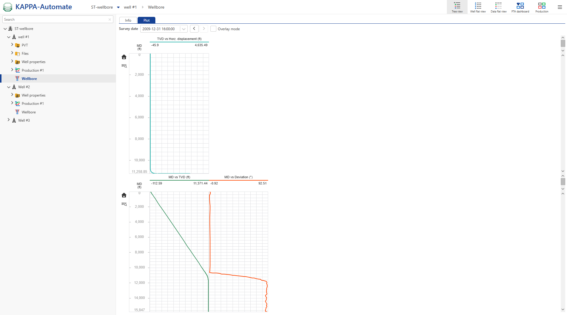
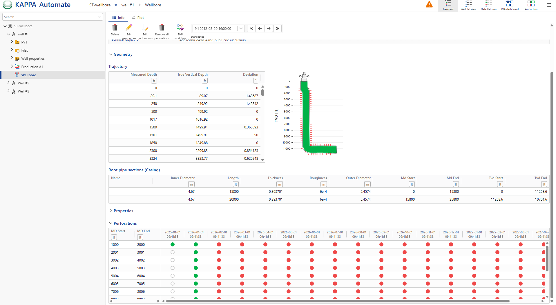
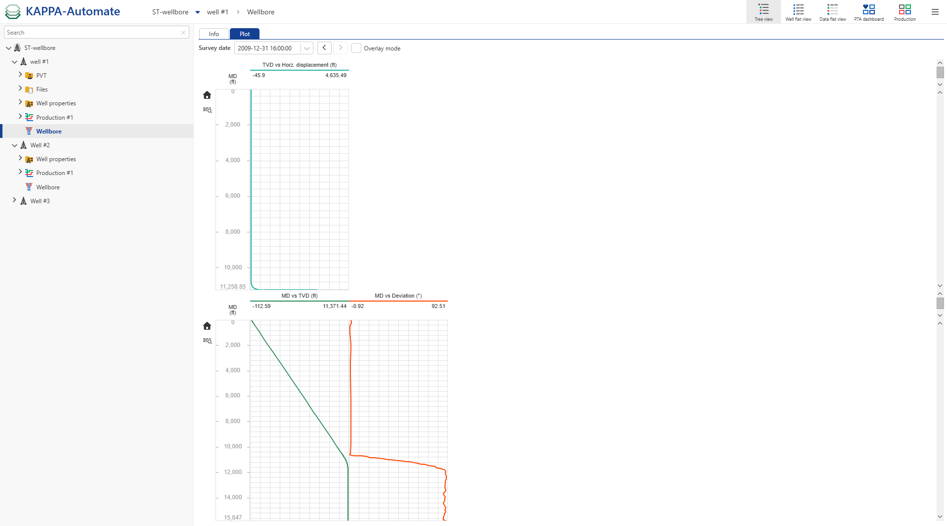
Trajectory table defines the wellbore path as a directionalsurvey. Each row represents one survey station with a measured depth (MD) and a true vertical depth (TVD). The inclination is computed internally from the MD/TVD pairs.
Pipe Sections
The Pipe Sections panel defines the well's pipe strings and their structural relationships. Pipe strings follow a two-level hierarchy: the root pipe represents the outermost section of the well, and an optional child pipe represents a pipe section installed inside it.
Hierarchy Rules:
The hierarchy is limited to two levels: one root pipe and one optional child pipe.
The root must be an Open Hole or a Casing string.
The child type depends on the root:
Root Type
Allowed Child Types
Open Hole
Casing or Tubing
Casing
Tubing
Each pipe string, root or child, can be composed of one or more segments, each defined by the following dimensions:
Property
Open Hole
Casing/ Tubing
Inner Diameter
Yes
Yes
Length
Yes
Yes
Thickness
No
Yes
Roughness
No
Yes
Geometry
Specifies the physical configuration of the wellbore along the depth. Each segment must define its structural state. Open hole, cased hole, or includes installed tubing.
For cased or completed intervals, define each string dimensions: Inner Diameter, Length, Thickness and Roughness.
Flow Path
Describes the production flow path in the wellbore. This isessential for production modelling and pressure loss calculations.
The flow path must be defined, e.g., though tubing, casing or annulus.
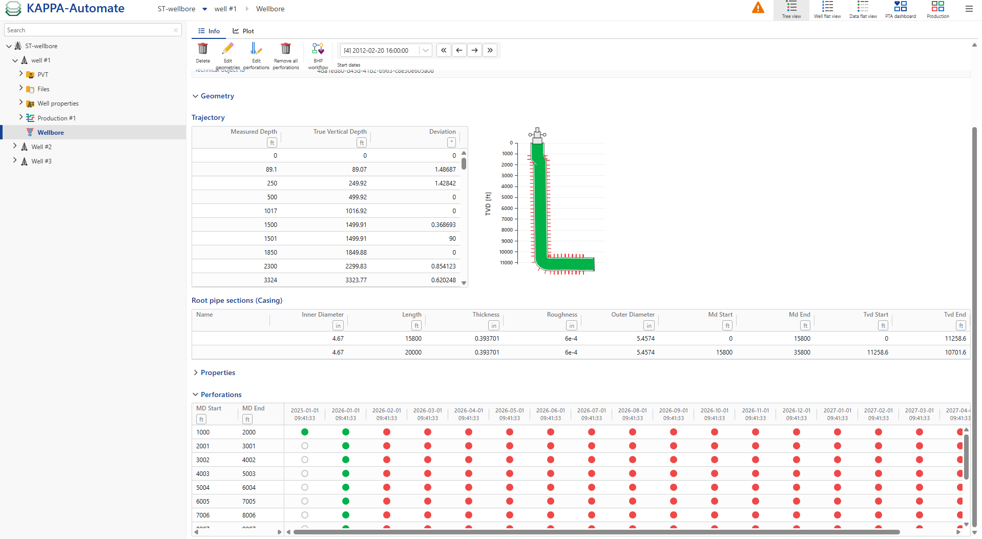
The Wellbore object includes definitions for gas lift valves, which are essential for modeling wells that use gas lift for production. It also allows the specification of perforation zones, which are used to generate inflow profiles.
Gas lift valve
For gas lift wells, the details of the gas lift valves can be specified:
Gas lift valve MD: This parameter specifies the installation depth of the valve and is mandatory when a Gas lift valve is defined.

Perforations
To define perforations, the following information must be provided for each perforation interval:
MD Start: Measured depth at the start of perforation interval.
MD End: Measured Depth at the end of perforation interval.
Is Open: Perforation status, open or closed (default is open).
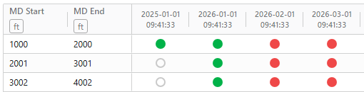
User can add or edit perforations during wellbore editing. To do so:
In the Wellbore node, click the Edit Perforations button ,
 .
.Modify existing perforations directly in the table using the status circles (
 = open,
  = closed,
  = not present at this date/depth).
Select multiple perforation rows and click on
 to update them in bulk.
Click on
 to create a new time‑dependent perforation state, then enter the corresponding date.
Use the
 or
or  icons to add or delete a perforation at a specific depth.
Click on
 option to copy an existing timestamp and its perforation configuration.
Procedure to create a Wellbore object
Wellbore objects can be created via the multi-well load process. This requires that wellbore data be stored in a database structured according to the KAPPA SQL schema.
Prerequisites
Wellbore data must be populated and available within the KAPPA SQL schema. It is strongly recommended to populate all available data fields, including non-mandatory ones. If certain fields are missing, default values will be assigned during the wellbore object creation.
Note
If casing or tubing data are inconsistent, KA applies default settings:
A default casing is added along the entire trajectory, with ID = 2 × TubingID.
The flow path is set to Tubing.
A warning message is displayed in the wellbore information page.

The mirroring data source and the multi-well load data source must be correctly configured and validated.
Procedure
Provide a Name for multi well load.
Select the Data Source.
Select the Tag (filters configured in the multi-well load setup).
Click Create.
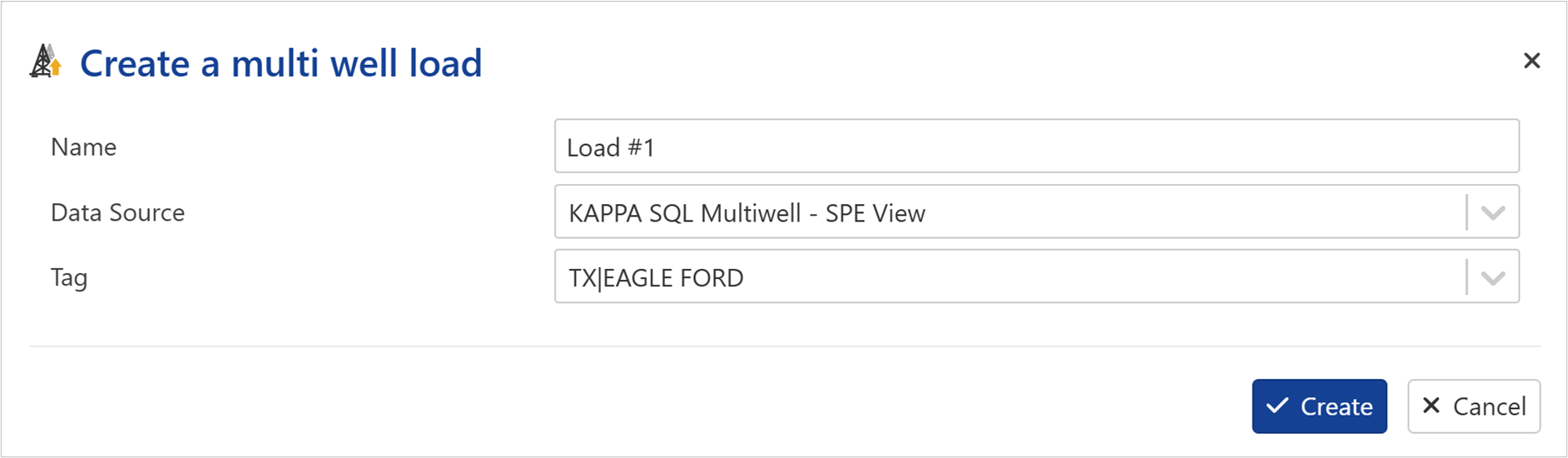
Once the multi-well load process is completed the wellbore object is displayed under well node.
Alternative method:
Using KAPPA-Automate SDK
Wellbore object can also be created using KAPPA-Automate SDK.
Prepare the deviation survey and wellbore geometry definition. If available, also include gas lift valve and perforation data.
Supported format include Excel files, which should follow the KAPPA Automate format.
Run the Python script.
Execute the script to process the input data.
Create the wellbore object.
The script will generate a Wellbore object under the Well node.
Inside KAPPA-Automate
A Wellbore object can also be created directly within KAPPA-Automate.
In the well node, click on Wellbore ,
 , under the Info tab:
Once created, the Wellbore object will appear under the Well node.
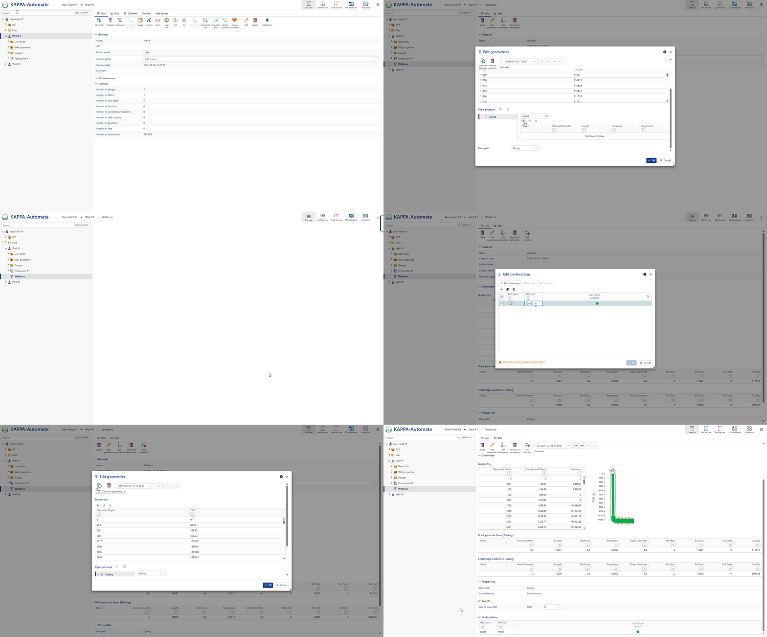
In the Info page, click Edit geometries,
 .
.
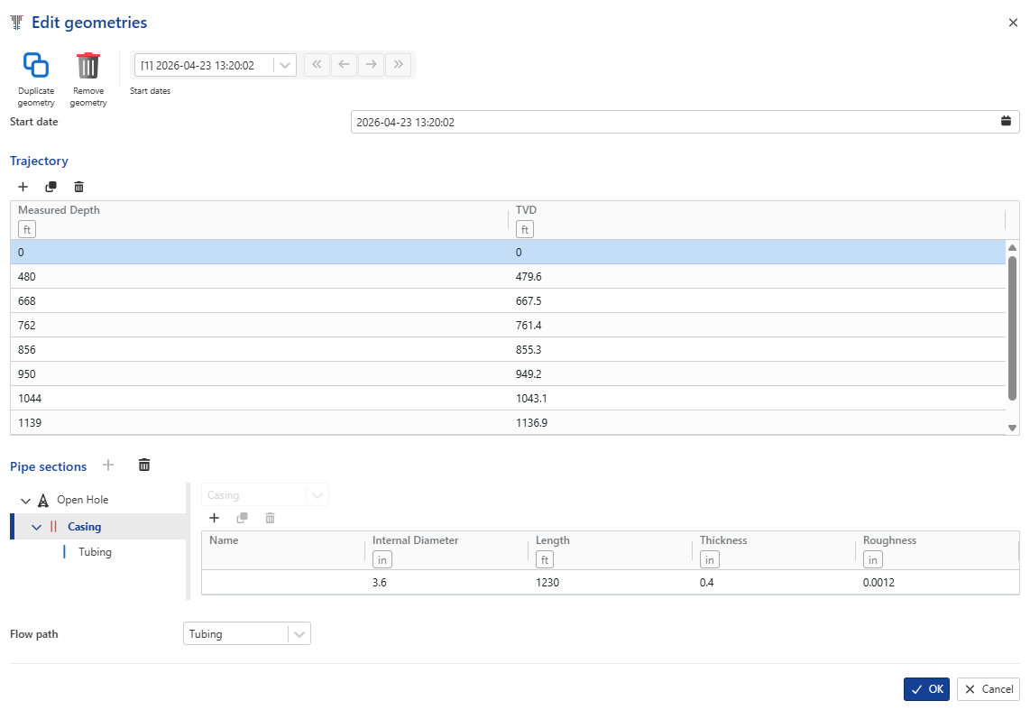
In the Edit Geometries dialog, the Wellbore Geometry tools are located at the top:

Duplicate geometry: creates a copy of the current wellbore definition. Use this to base a new wellbore on an existing configuration (e.g., after a workover) without re-entering all data.
Remove geometry: Permanently deletes the current version. This action cannot be undone.
Navigation arrows: Navigate to first, previous, next, or last time-dependent wellbore version without opening the dropdown.
Open the Start date panel to set the wellbore completion date.

Define Trajectory:
Click
icon in the Trajectory toolbar to add a survey station row.Use the
or  icons to copy or delete a survey station row.
Enter MD and TVD for each station. Repeat this process for all survey stations.
Alternatively, the entire trajectory can be pasted directly from the clipboard: select the first cell of the MD column, then paste.
A minimum of two rows (surface at MD=0/TVD=0 and total depth) is recommended for accurate BHP calculations. Units are determined by the field unit settings.
Define Pipe sections
Add root pipe:
Click
icon next to the Pipe sections header. A root pipe section node is created.Use the
or icons to copy or delete pipe section.The node type defaults to Casing. Confirm it is set to Casing in the type dropdown.
In the detail panel on the right, click
to add a dimention row to the casing node.Use the
or icons to copy or delete a dimension row.Fill in the row fields: Section Name, Inner Diameter, Length, Thickness and Roughness.
Add additional dimension rows for each distinct casing segment if the pipe dimensions change with depth.
Add the Child Pipe:
In the Pipe sections tree, select the root Casing node.
In the detail panel, click
to add a child node inside the selected Casing node. It defaults to type Casing.Click the type dropdown and change it from Casing to Tubing. The tree node name updates automatically.
Click
to add a dimension row to the Tubing node and fill in the fields. The tubing Inner Diameter must be less than the casing Inner Diameter.
Note
When a new row is added, the UI populates placeholder defaults (typically ID = 3.6 in, Thickness = 0.4 in, Roughness = 0.0012 in). These are not recommendations, replace them with actual completion data. Outer Diameter is a computed field and only appears in the saved Info page, not in the edit dialog. At least one dimension row is required in the root pipe section. Saving with an empty root pipe table produces the error: "Null item: Either root pipe or child pipe has to be defined to create a geometry”.

Define the Flow Path
Select the flow path from available options: Casing, Tubing, Annular.
Default value is Casing, regardless of whether a Tubing string was added.
Tubing flow path is required for injection valve depth to be physically meaningful.
Define Gas Lift Equipment
This section is hidden by default and must be unlocked via a checkbox.
Scroll below the Flow path dropdown to the Gas lift equipment section.
Check the Gas lift equipment checkbox. The Injection valve depth field appears.
Enter the measured depth, MD, at which the gas lift valve is installed.
Note
The field is labelled Injection valve depth in the edit geometries dialog and Gas lift valve MD in the Info page. Both refer to the same value
Click on OK.
The new wellbore is created.
Info tab:
Plot tab:
All steps are shown in the .gif below.